I’ll admit it – I’m struggling. I’m experiencing some kind of “builder’s fatigue”. For the past month or so now I’ve been doing nothing but bodywork – and it just doesn’t seem like I’ve been making all that much progress.
Typically, I have a rough idea of what I want to do over the next several days or week and I work to those each day. Since feeling this “builder’s fatigue” I thought maybe I just haven’t been organized enough about my daily goals and this is the reason I’m feeling like it’s so never-ending. So I made a list of to-dos and jotted them down on a piece of paper. I’ve been steadily knocking things off the list but it doesn’t seem to be happening as quickly as I expect it would. I’ll be in the middle of working on a to-do item and I’ll see another thing that needs addressing, so I’ll start working on that. Then I see something else and I shift over to that. It’s like a kitten pulling on the thread of a ball of yarn – there’s just more and more yarn! So sadly, the struggle is real, it really is never-ending. Keep kicking the ball.
Doors:
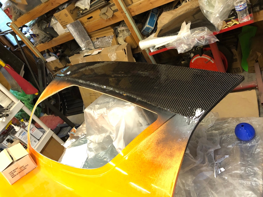
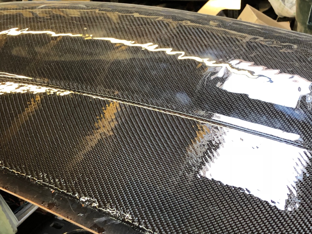
Carbon. More carbon! I’ve already typed enough about carbon so I’ll just let the pictures (and captions) do the typing.
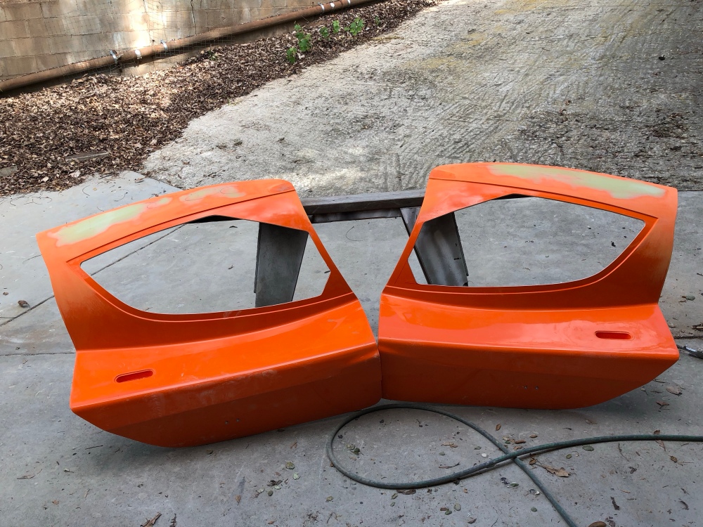
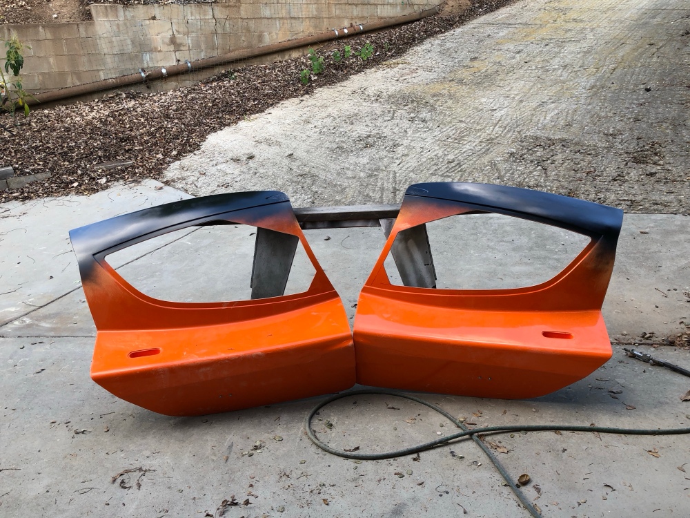
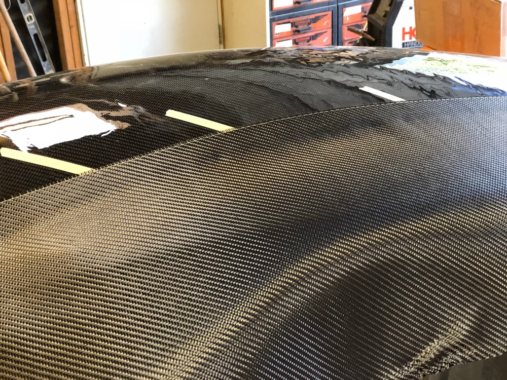
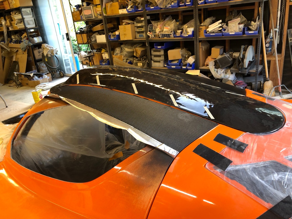
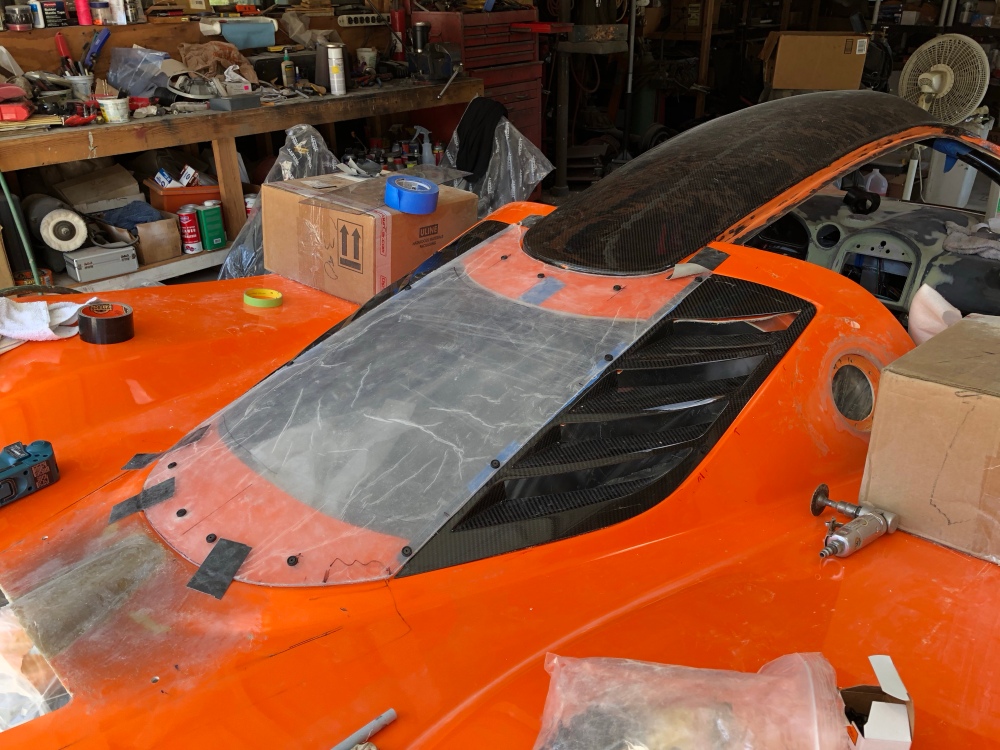
Doors getting prepped for carbon. There are low spots running along the upper edge that needed filling up.PaintLaying down the carbon sheet. I used white tape along the roof to help make the weave more visible. I then set the carbon sheet on the door down to try and match the weave orientation.Tacked and trimmed. That small orange area between the door and rear glass will also get a small patch of carbon, then the roof panels will be fully carbonited!! (I just recently rewatched Return of the Jedi, forgive my terrible attempt at bringing in this geeky reference).Wet out coats down – very minor wrinkling. Phew!It’s a pretty decent match between the roof and doors!
Rear clam:
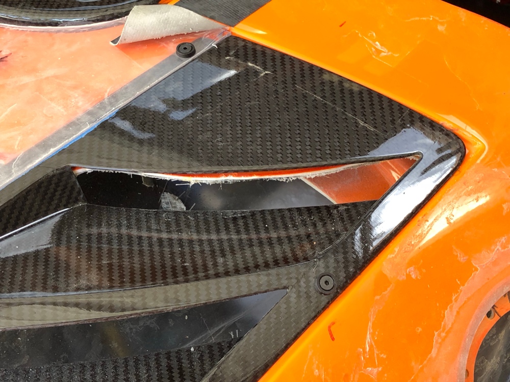
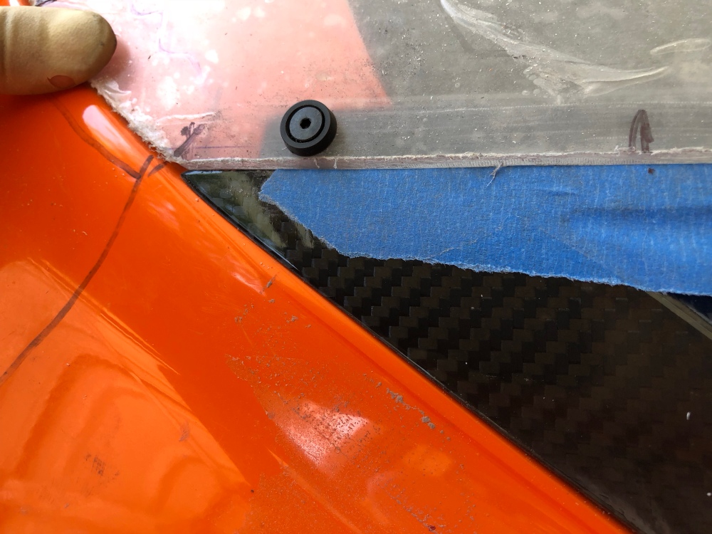
In post 27 I had started installing the rear window louvers. There are several ways to install these louvers. Here is the installation method as described by the manual. In it, the builder uses double sided tape to secure the exterior edge of the louvers. As mentioned in the manual, this is a semi-permanent installation method. I’m guessing if you needed to remove the louvers they would likely crack when pulling up on the double sided tape. I didn’t like that idea, so I opted to go with using some fasteners instead.
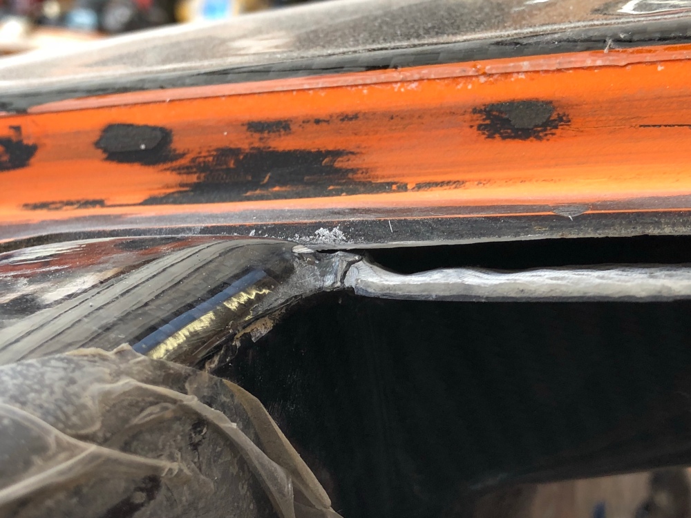
HOWEVER, there is an issue with my installation method. The louvers are designed to sit on the rear glass along the interior and exterior edge. To facilitate placement of the center glass, and to avoid having a visible step between the two, the interior edge is stepped on the louver and the rear glass sandwiches the louver into place. As you move from the interior edge toward the exterior, the outer surface of the louver should be flush with the outer surface of the rear clam. However, once you hit the exterior edge, in order for it to remain flush with the exterior surface, some material added between the louver and the rear glass depression. If installing with double sided tape, that’s no problem – the tape is thick enough to push the exterior up so it’s flush. When securing with fasteners a shim would need to be made.
The shim needs to extend all along the exterior edge and needs to blend down to nothing as it reaches the interior. A “simple” way to do this would be to add reinforced resin all along the perimeter and sand it back as necessary. Uuungh – simple but lots of work. So I said screw it and just bolted the louver down without any step at all.
For all my OCD bells going off, it didn’t turn out too bad at all, but it’s definitely a compromised look.
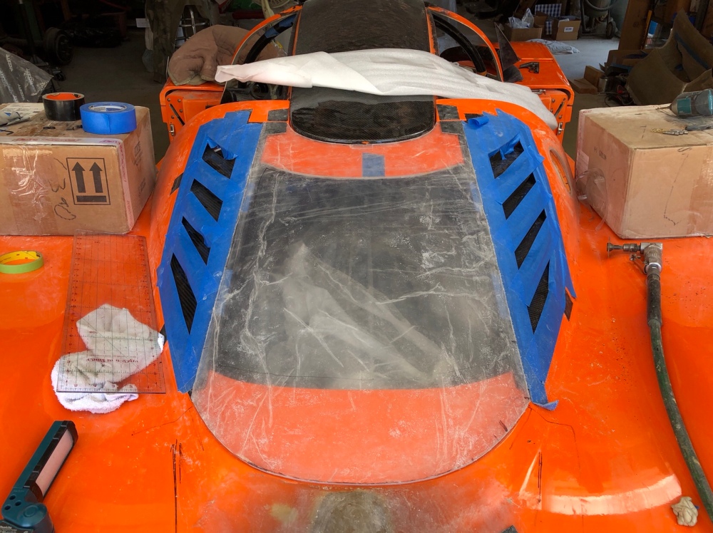
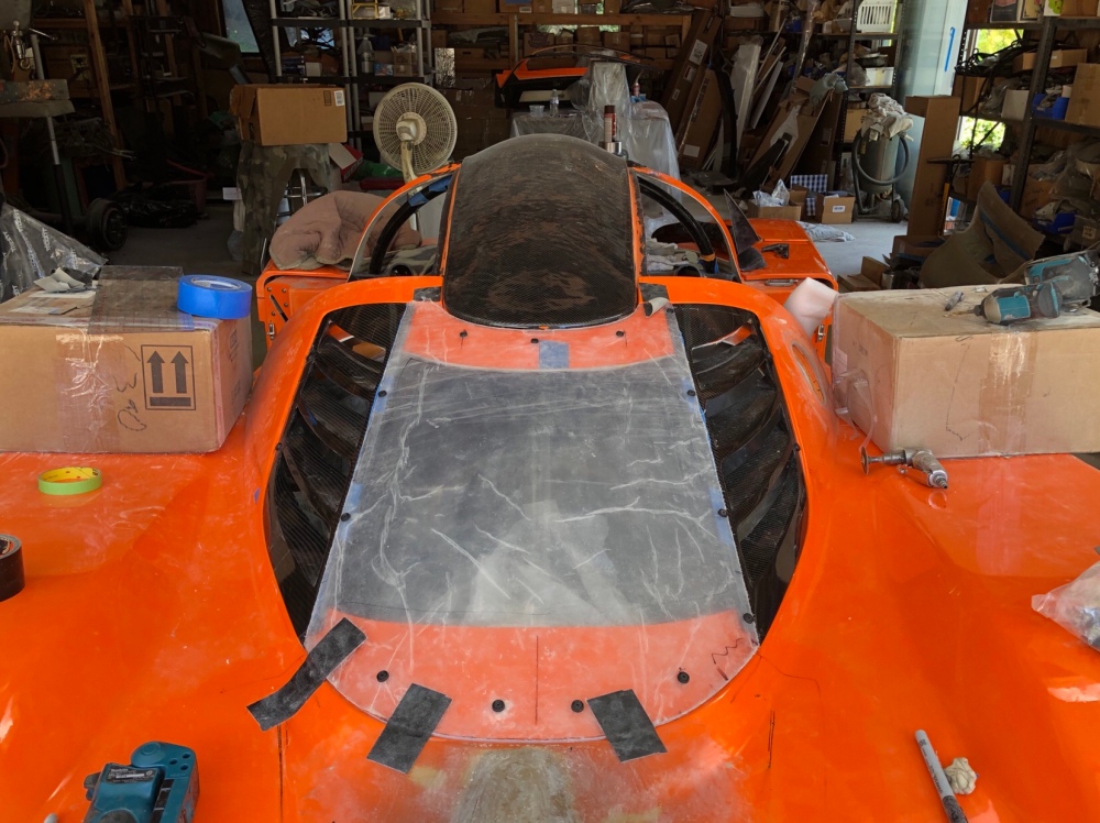
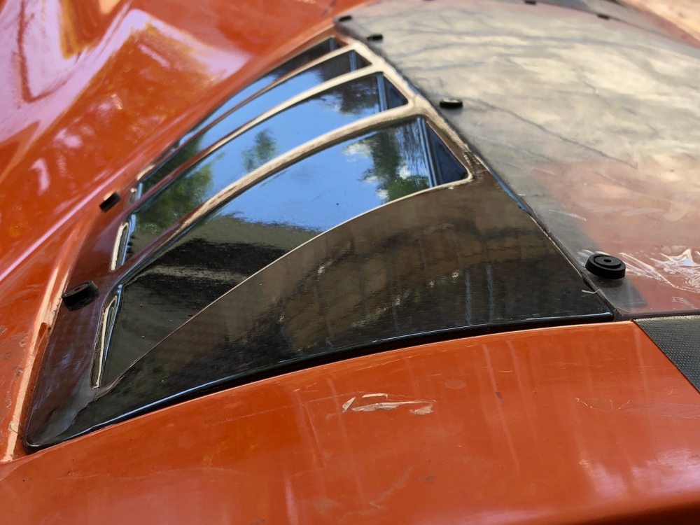
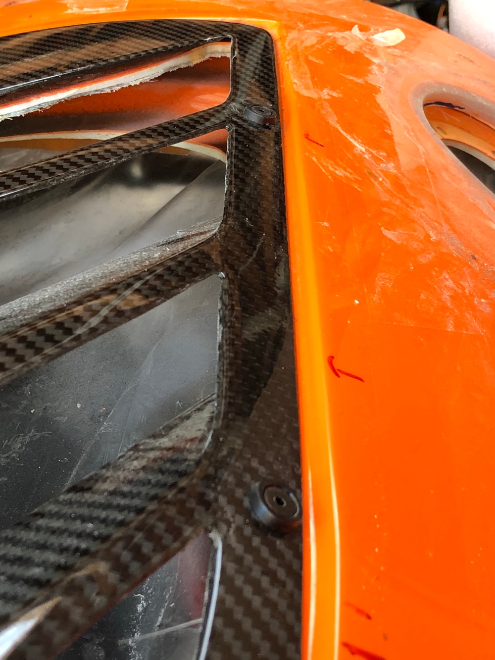
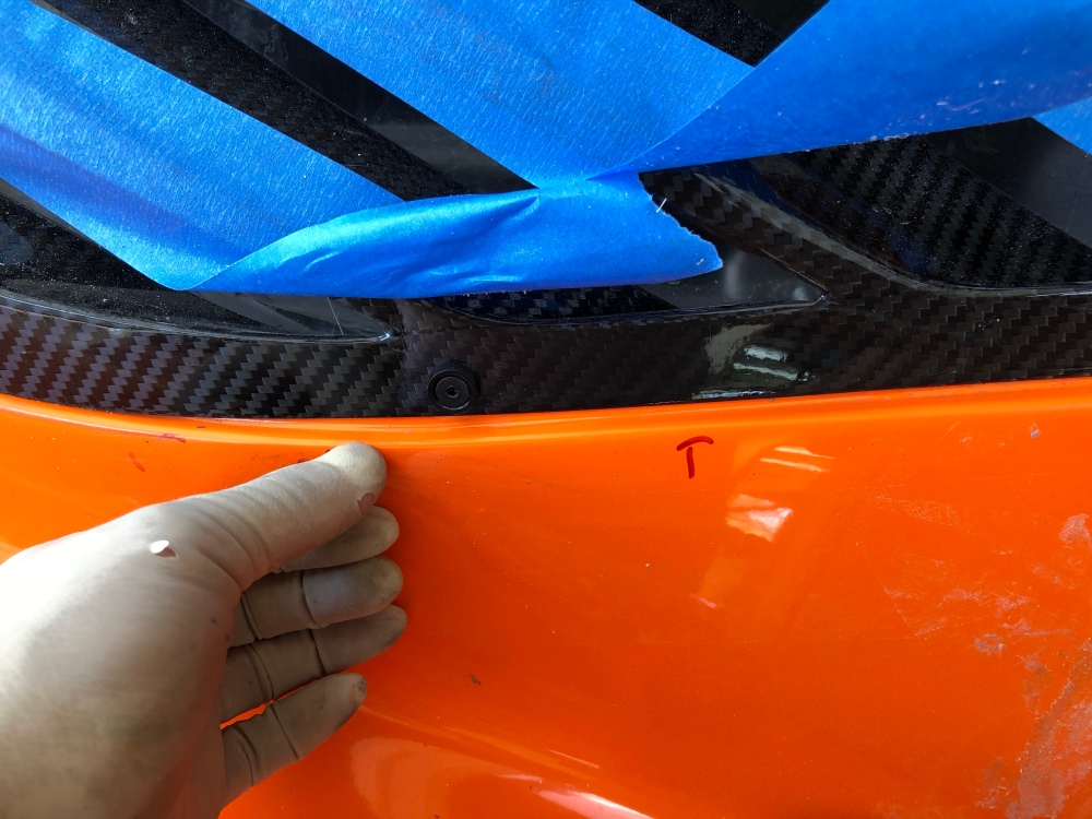
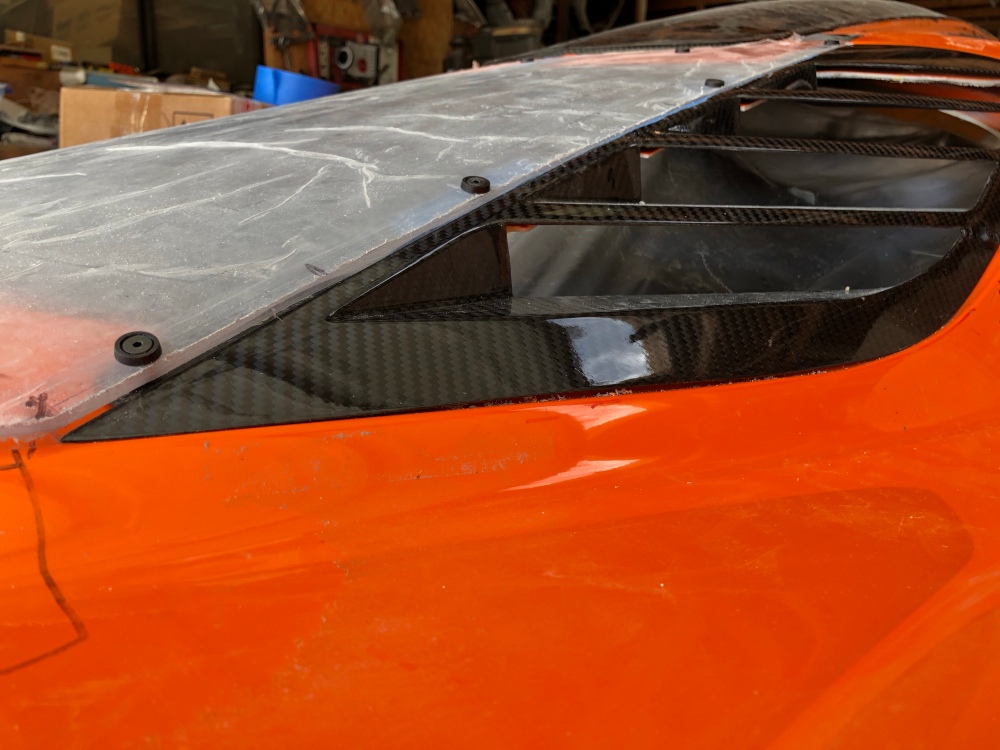
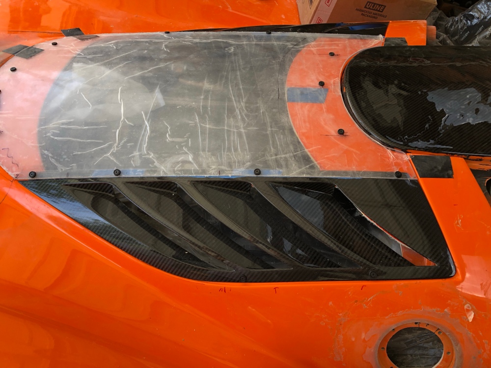
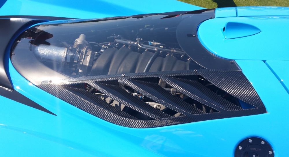
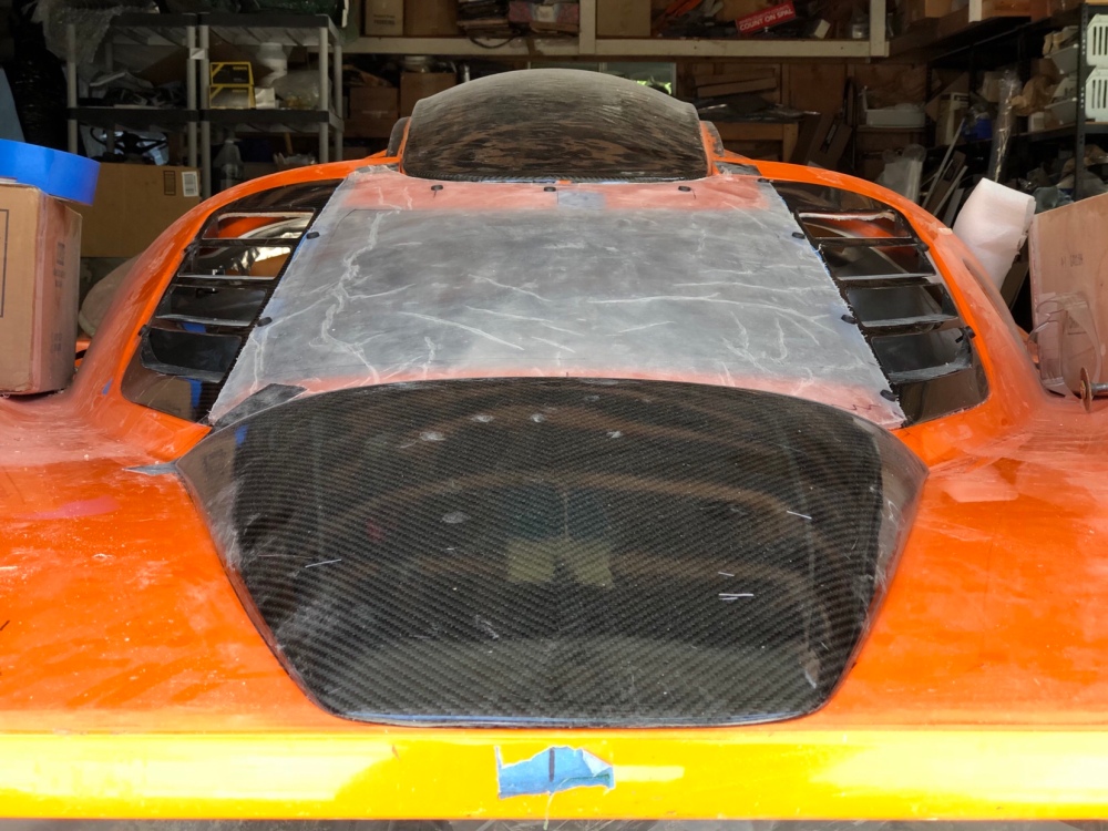
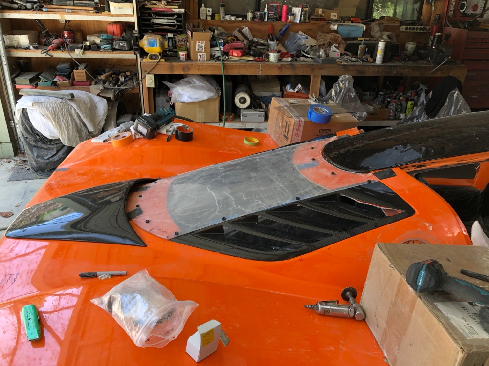
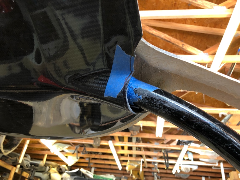
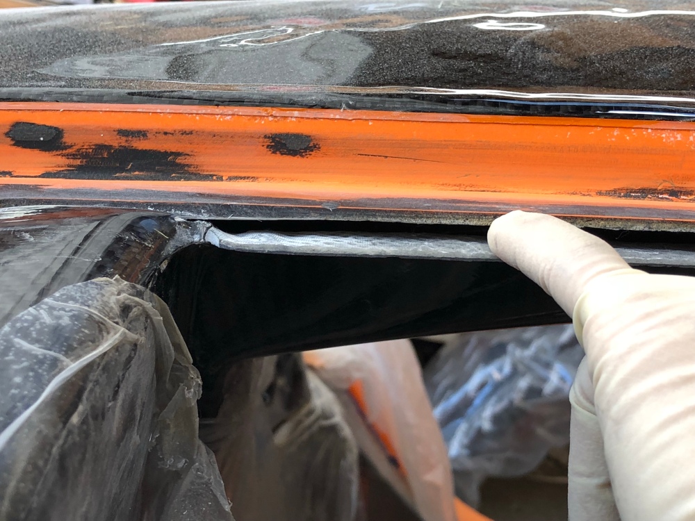
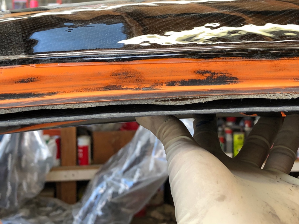
To trim the glass, I followed the manual. Blue tape applied to the vents so you can place the glass on top and mark the cuts without scratching the louvers.Installed. Some minor trimming of the lower edge of the glass was needed. I found the best method was to rough cut the glass, then using a large flat sanding block, sand the glass back with 80-grit until it fits. Come back later with progressively finer grit sandpaper to smooth the sanded edges.You can see the fitment issue I described earlier by looking at the above photo. The interior edge pushes the carbon surface up to meet the glass and hatch surfaces. As you move toward the exterior, there’s no step down to meet the lowered surface.This angle shows the issue better – the exterior edge is now no longer flush with the rear clam’s outer surface because the relief meant for the thicker glass is now too low.Looking “up” from the lower portion of the louver. The louver sits below the clam’s outer surface along the entire length. Note how a small gap forms near my lower screw.The gap is much more apparent when stepping back. There is a slight contour mismatch here which is caused by my installation. To get the exterior edge flat against the hatch, the louver needs to be installed slightly cockeyed.Back along the interior edge, it comes back up to meet the exterior surfaces of the hatch and glass.(Screws not secured in this photo, just installed to help locate the glass while drilling my holes). The fit is very nice along the lower edge.Fitment using fasteners and no shim – the only visible issue is the slight contour mismatch along the exterior edge. I will be painting the lowered portion of the rear hatch in black and that ought to hide this contour mismatch fairly well.Fitment using double sided tape – the contour is better matched at the expense of a permanent installation.Another angle.For giggles I threw on the rear intake scoop. The rear glass is surrounded by carbon on all sides!Another angle.
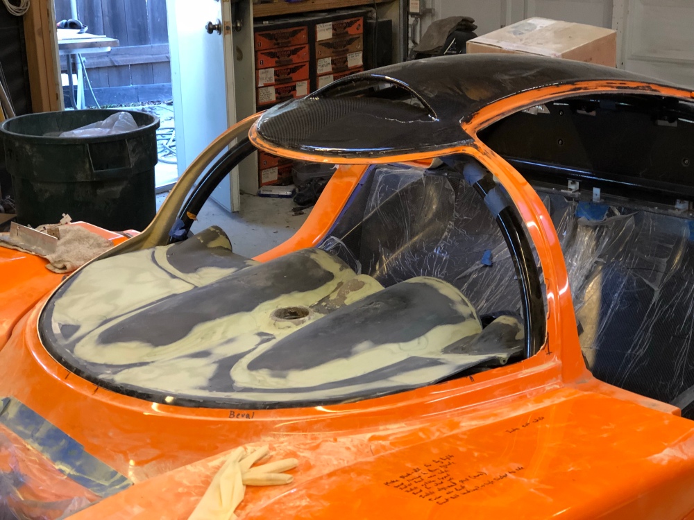
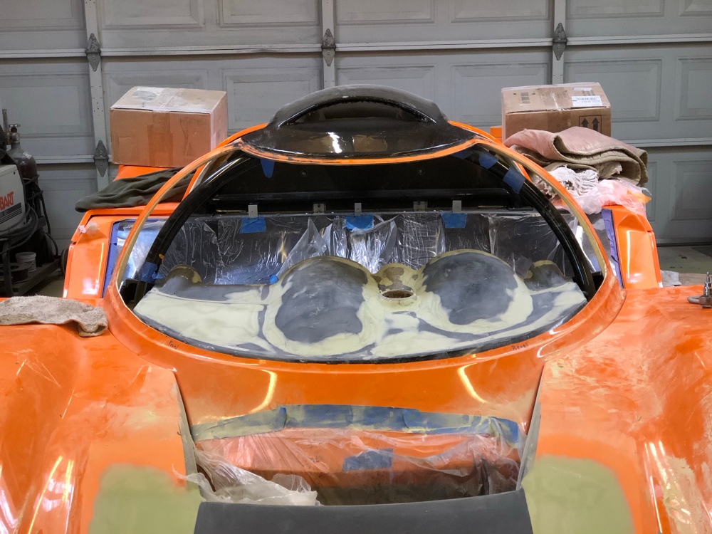
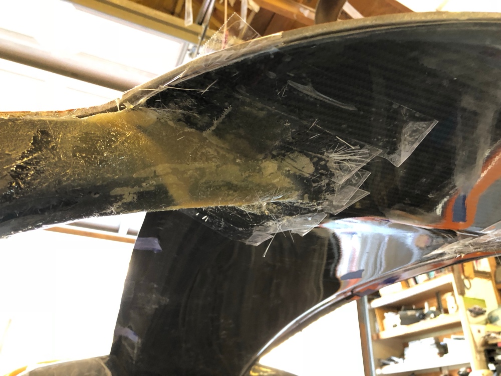
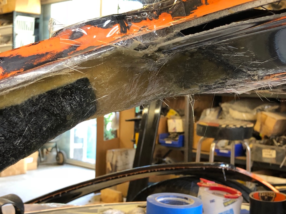
Also in post 27, I mentioned how I was considering adding some more material to the rear glass based on another builder’s attempt at stiffening the rear structure. I did that, and I didn’t do it very well apparently.
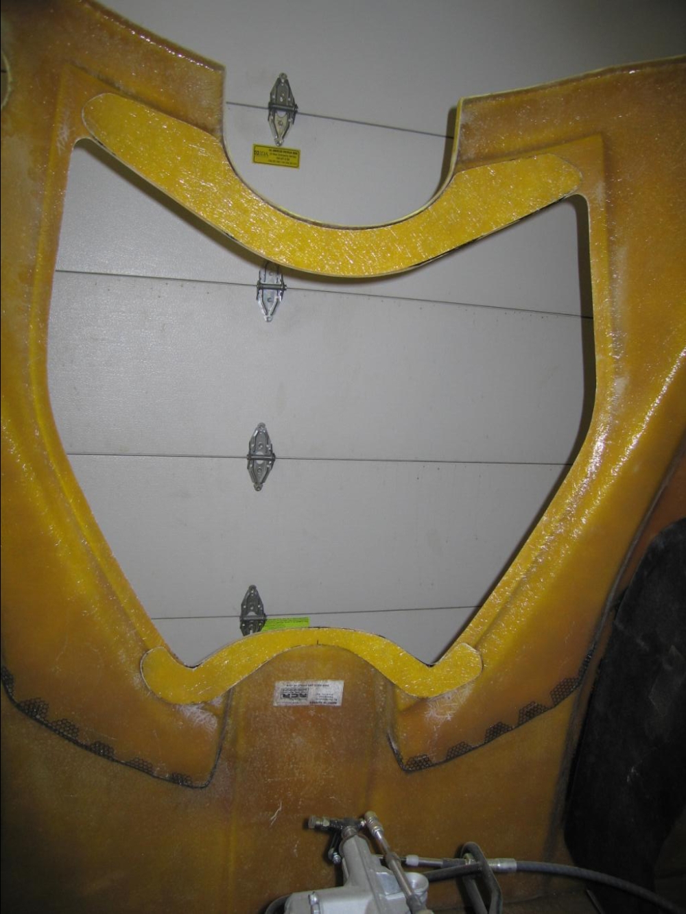
Here’s the stiffening that I was attempting to replicate (this is of a street tail). The two lighter sections of yellow are stiffening pieces bonded to this builder’s rear clam.I figured I would be over-zealous and add a lot more stiffening! So I plotted out the locations for my extra material and made templates, ensuring good overlap between each piece.Ta-da! Stiffened rear … or so I thought. It still felt somewhat flimsy to me (without the rear glass installed). When I did a test fit and open with the rear hinge installed, it still required 2 people to lift the rear glass up without it binding on the alignment pins. After I put the this photo up on the GT40s website I was asked if I had added any 3-dimensional stiffeners – whaaa? So it’s a technique you can use if you know what you’re doing (I don’t). Place some resin-safe pieces down on the body, then apply your fiberglass on top. Something like a soda straw – anything to make the extra glass 3-dimensional. That’ll really stiffen things up. Wish I had known/thought to do so before adding all this glass! It’s a bit tight between the rear clam and the spider now so I’m afraid there’s not much room left for me to continue adding stiffeners. I’m going to leave this for now and possibly revisit it at a later time. Or just live with it and move on.
Wheel recontour – v2.0:
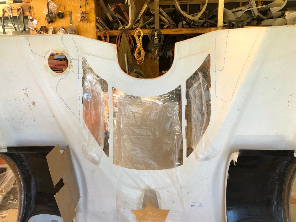
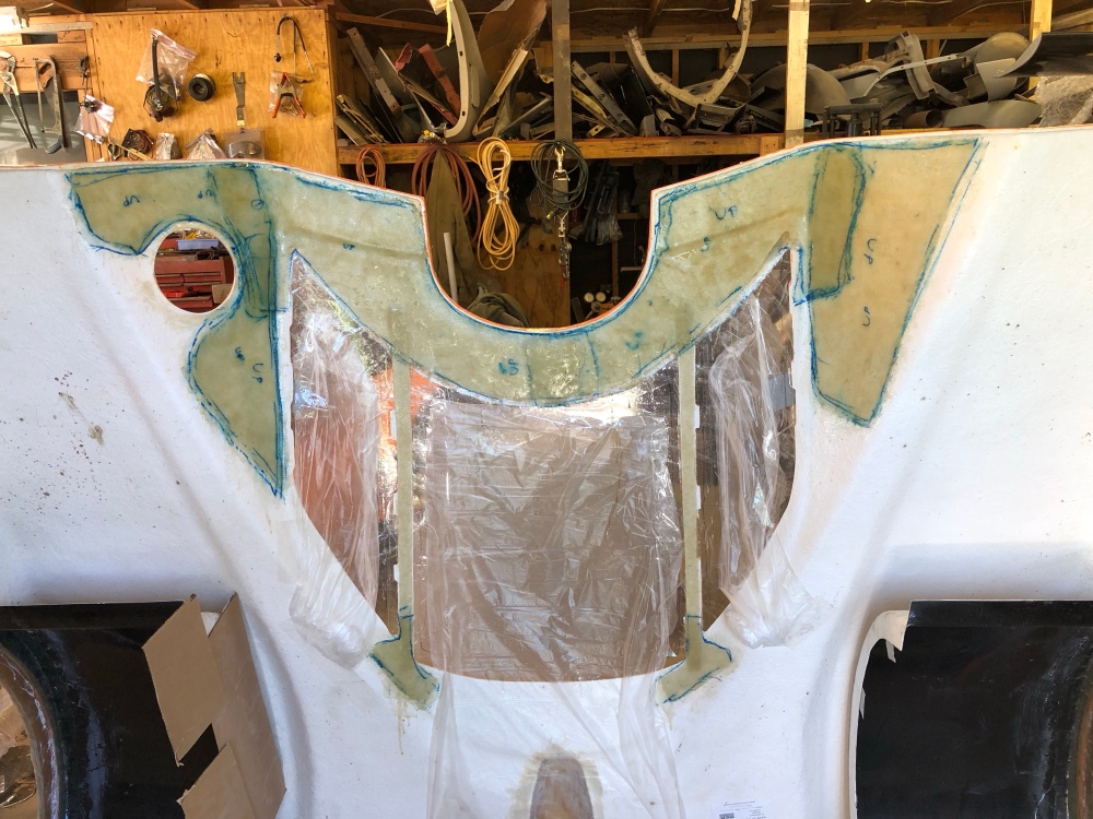
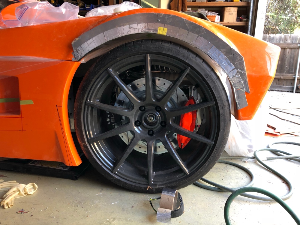
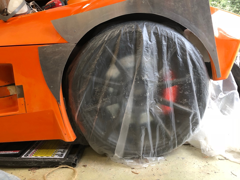
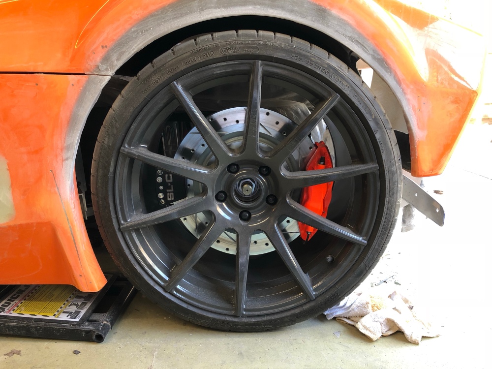
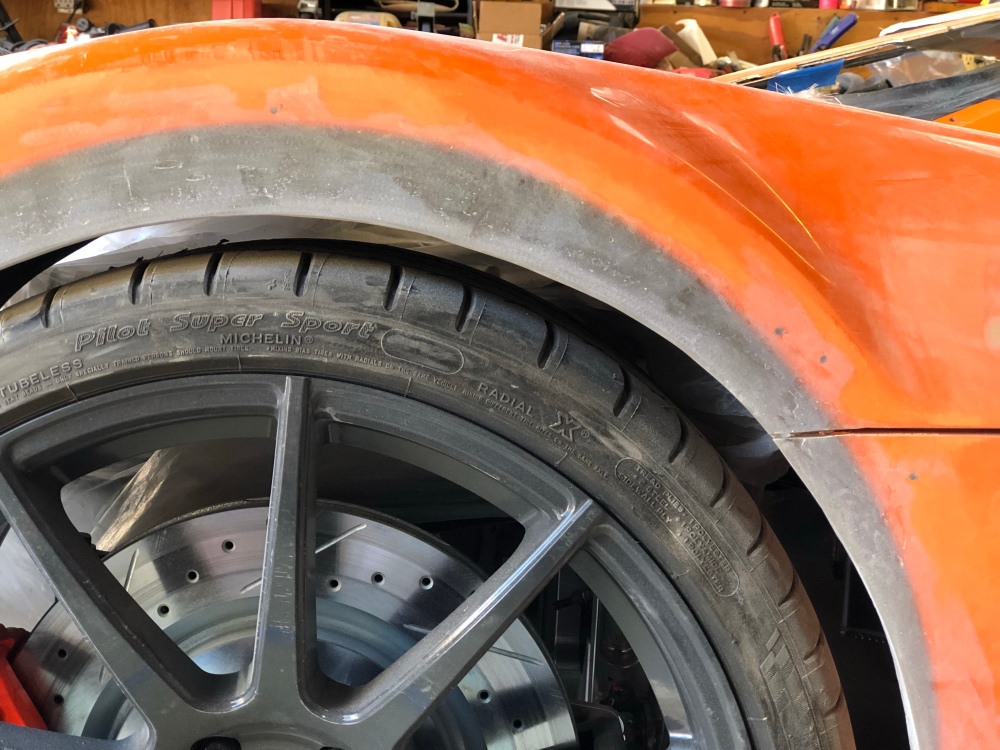
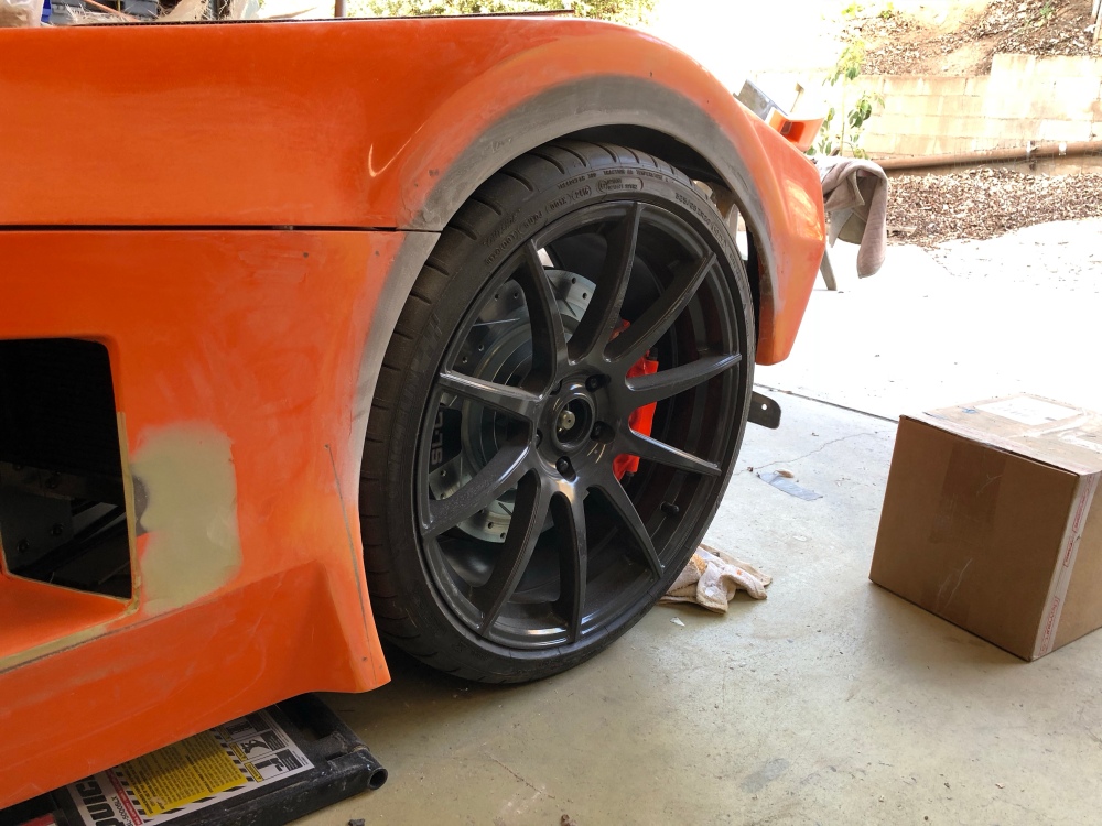
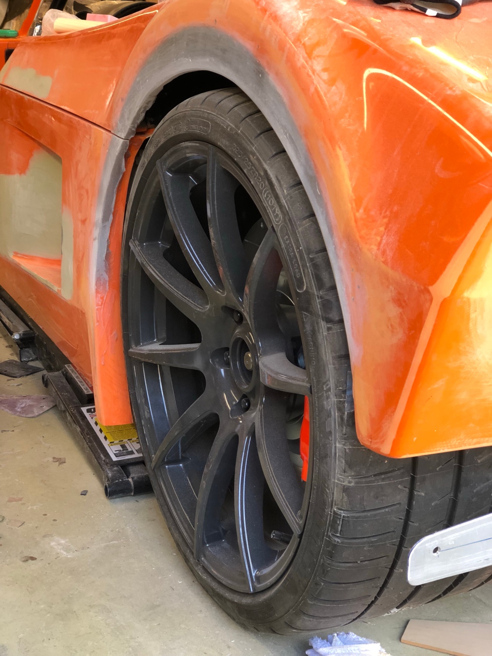
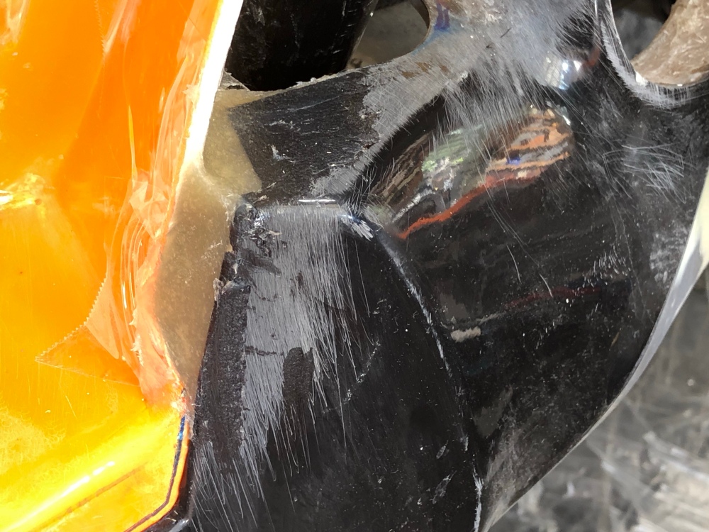
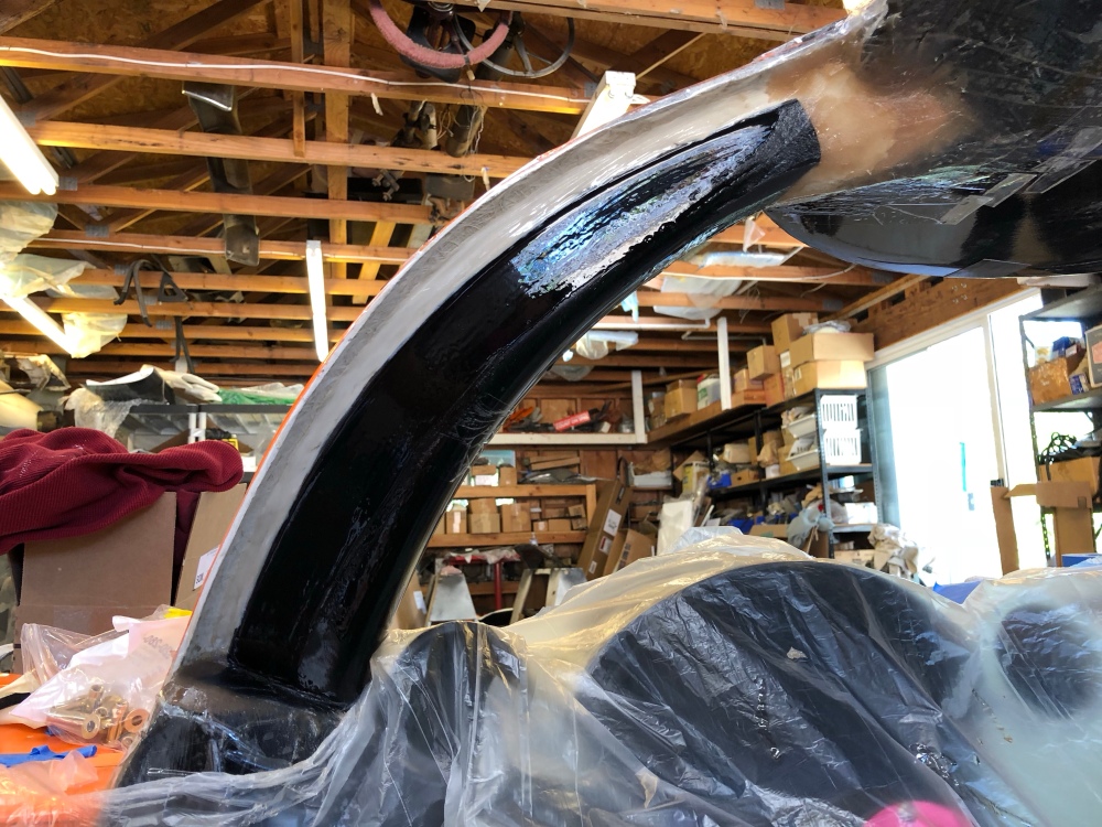
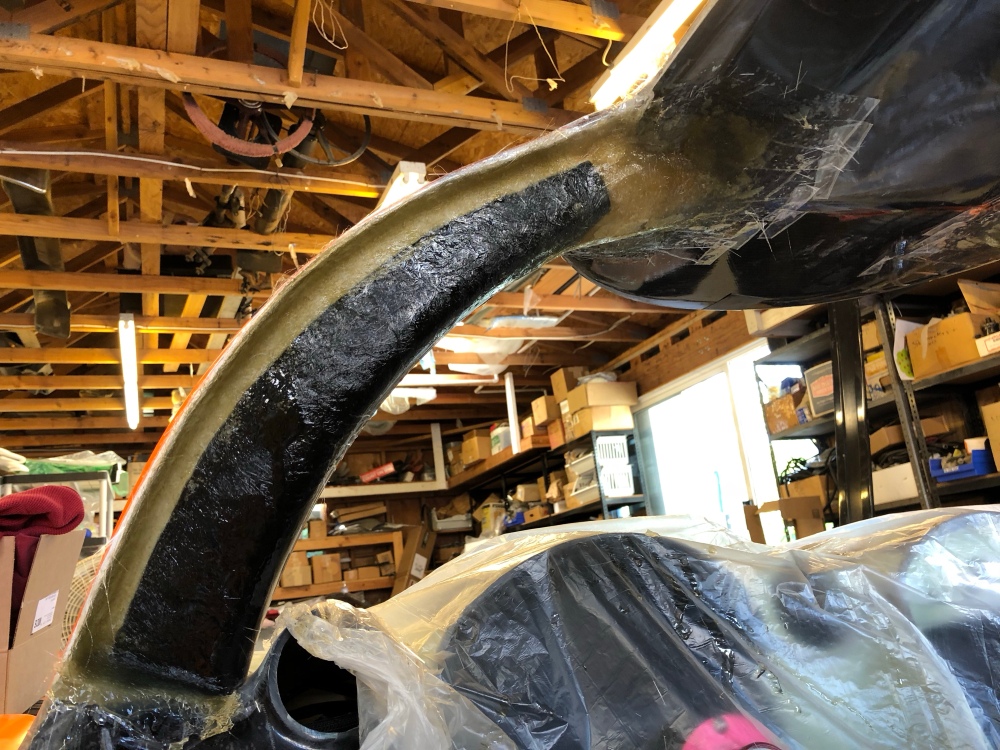
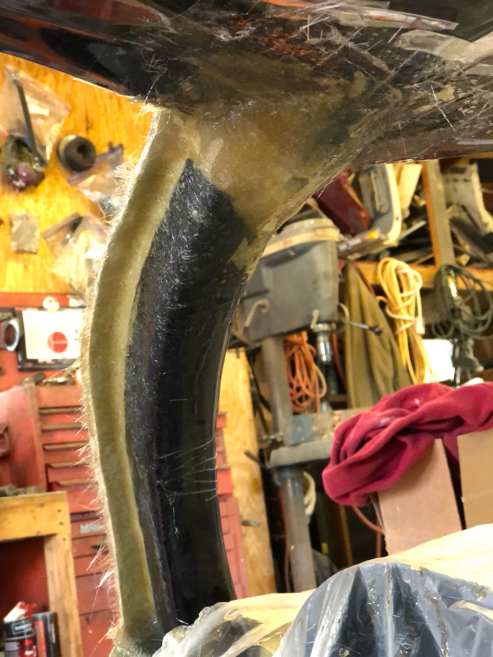
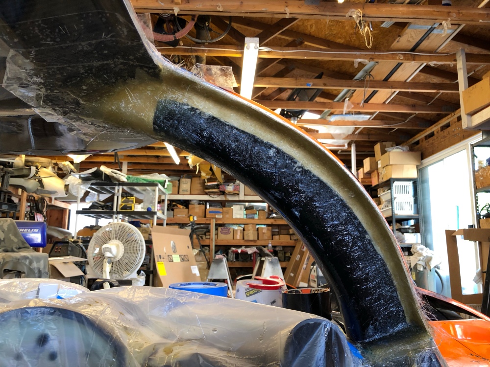
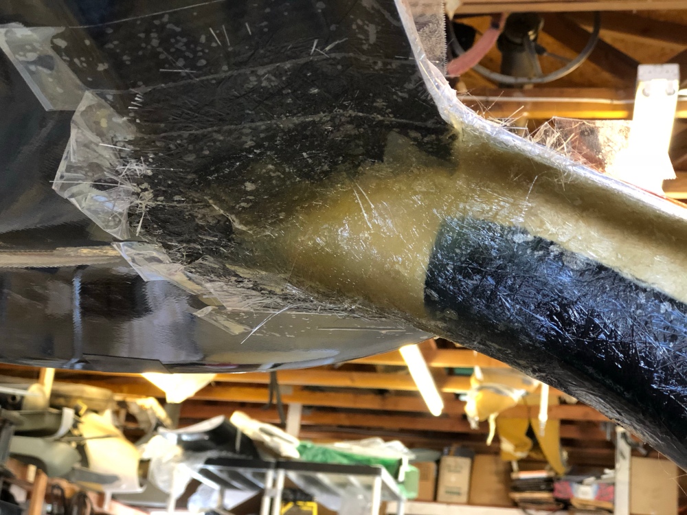
Also in post 27, I discussed how my rear wheel wells looked so messed up with my ride height of 5.5″. My first attempt at reshaping the wheel well had me trying to preserve the forward and rear areas of the factory contour. So I was basically going to “drop” the top of he contour down, sort of like cutting the long side off an ellipse and attaching it to the original circle. It didn’t look very good …
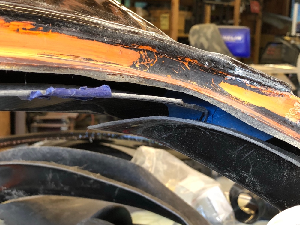
My original attempt at reshaping the contour. I didn’t want to massage the part of the contour attached to the center spider (lower edge excluded). After removing my template it looked just as ugly as it did with the template …… so I took another stab at reshaping the contour, this time sucking it up and extending it across to the center spider as well.New contour roughed in. Still needs a little more clean-up once I get the tail off for more fine tuning. I also still need to verify the tires won’t hit this new profile during suspension compression.Closer shot showing how much I’ve dropped the contour down from the original bodywork. To get the shape as consistent as possible, I glassed across and “joined” the rear and center pieces temporarily, then split them at the seam. Note how much material I’ve added just to get a halfway decent gap, it’s almost twice as thick at the top of the arch! I must be running a higher ride height than any other SLC out there because I’ve never seen a wheel gap as bad as my car. I live in a hilly part of town and I need all the ride height I can get.Another angle.And another.
Dash:
My electrical work has been a bit delayed since I last (and first) drove the car. I’ve been putting off doing much more until I could get the interior figured out. Locating the buttons in particular were necessary before I could start running my switches to where they’ll end up.
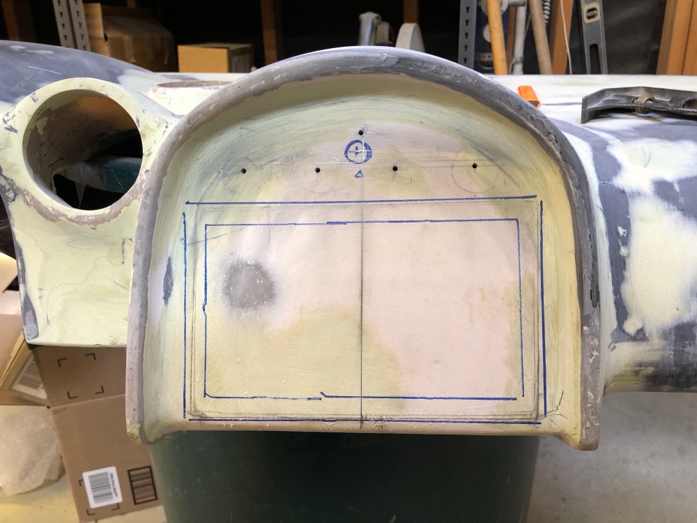
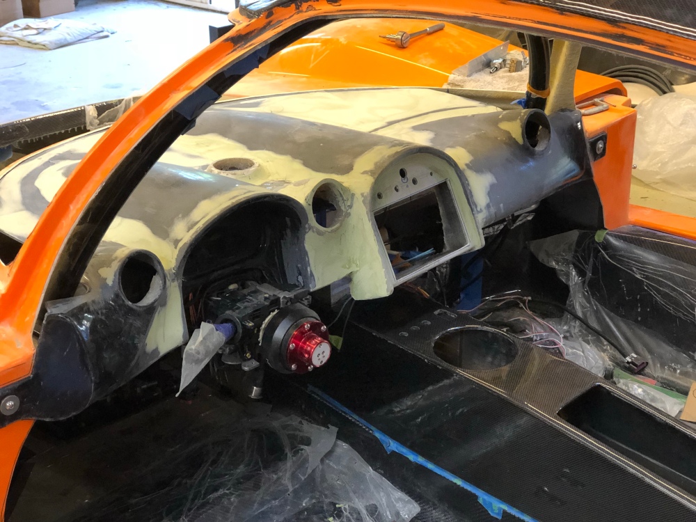
I think if there were an award for “Excessive use of body filler” for the dash, I would be a sure winner. I had hacked mine up so I could shift the center binnacle over about 3 inches. In doing so, I caused the dash to no longer be flat left to right. This put a few whoopties across the surface. There’s also a good number of deep lines running across the dash which highlights the various contours and sections of the dash. With as wonky as my dash is, these hard, defined lines were not so good for hiding all my mistakes.
So I wiped them all out using body filler! By making everything softer and getting rid of hard edges, it’s a lot more difficult to pick out surface inconsistencies.
Marking out my cut lines for the radio display and climate control buttons.There’s gold in them there hills – Evercoat Rage Gold (body filler) that is! You can see how all the sharp lines have been eliminated with body filler. The interior is starting to look a whole lot better with the dash and center console installed.It almost looks flat going from left to right. With enough bondo anything looks good!Going for the simple and clean look.
A-pillar covers:
Ooof … this is another one of those “what the heck is going on” situations. I don’t recall reading too much about others’ experiences with the a-pillar covers but mine simply do not fit – at all. I spec’d the carbon fiber tub and fiberglass a-pillar covers. My assumption is that they are cross compatible, but this may not be the case, and may be the reason why my parts fit so poorly (or don’t at all, as is the case).
I’m super relieved I went with the fiberglass a-pillar covers because I’ll need to do a LOT of modification to get a halfway decent fit between everything. Had I gone with the carbon covers there’s no way I’d have been able to make any modification without ruining the carbon. It would be interesting to hear from anyone who’s purchased the carbon a-pillar covers to get feedback on how they fit.
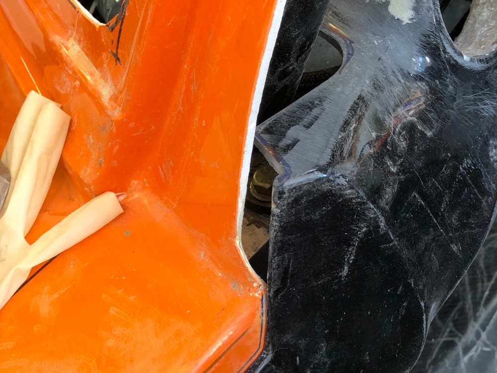
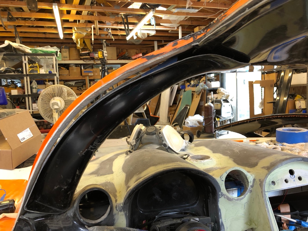
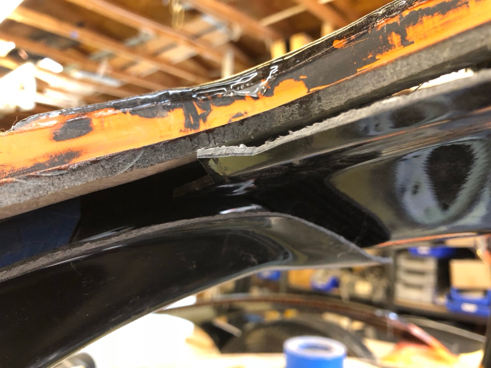
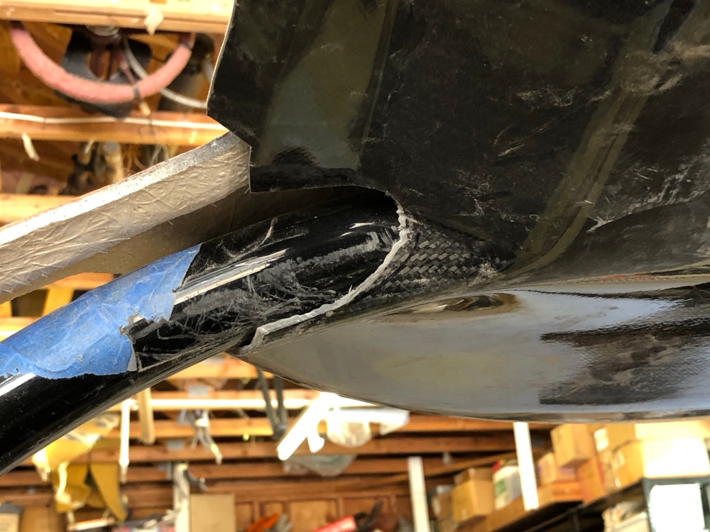
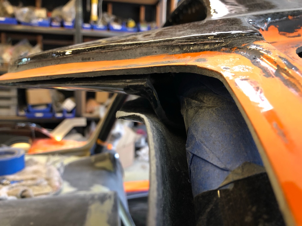
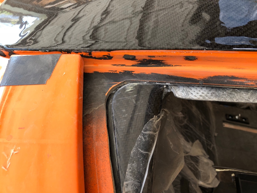
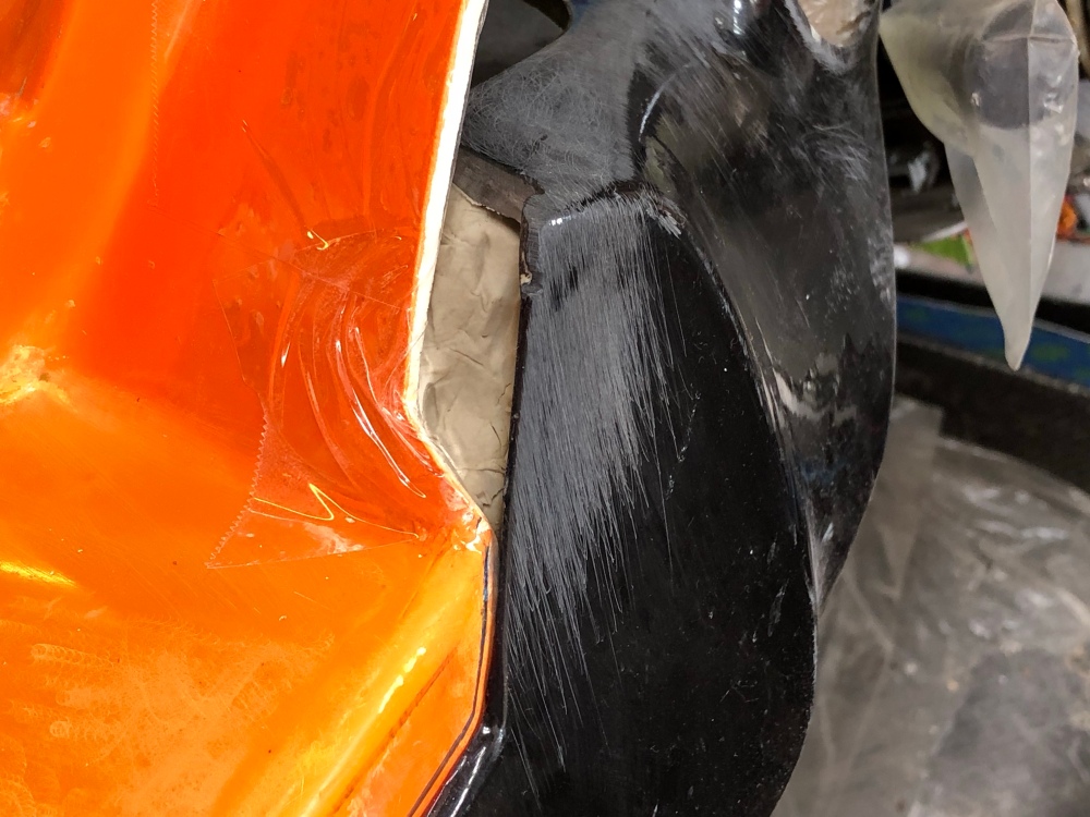
Orange gelcoat was trimmed by the factory and I did a small notching of the dash panel. However, there’s going to be a pretty big hole where the two meet, and this surface is exposed to anyone looking into the car once the door is opened.The best fit I could get after SERIOUSLY hacking the roof panel. You have to be super careful when cutting the ceiling panel (if you went with the carbon option, as I did), because you can’t glass it back together and make it look nice without totally destroying the carbon. Going all fiberglass panels would have been the easiest option so you can cut and modify as necessary to get the perfect fit. Gaps range up to as much as 1 inch.Close-up showing where the exterior, ceiling panel, and a-pillar cover meet. The a-pillar cover can’t sit flush with the ceiling panel because it’s simply too small to sit flush against the ceiling. Both panels want to occupy the same space.Here’s the same shot with the a-pillar cover removed. I had to seriously cut the ceiling panel to get it to fit over the roll bar. You can see just how much scratching I did to the roll bar from messing around with the ceiling panel. I would cut a small bit off then do a test fit, rinse and repeat, rinse and repeat. It took a lot of trial and error before I could get a decent fit that would allow the forward part of the ceiling panel to mate nicely with the spider.I didn’t have to trim nearly as much material for on the passenger side. However …… the a-pillar trim also did not fit. I call this area the “Nexus of things that don’t fit”.On the forward side of the front roll hoop, the a-pillar cover also doesn’t fit. Here you can see the interior dimensions for both the ceiling panel and a-pillar cover – they’re both the same! One of the two needs to be eliminated for both pieces to fit – there can only be one! (That’s a Highlander reference …)Further back, the story isn’t super great either. The spider was trimmed too far back from the factory. To get the ceiling panel and spider interface looking good I’ll have to fill this back in with reinforced resin – not a big deal.But here’s a shot showing the joint between the exterior edge of the door opening. By design, there’s a pretty good gap between the two that can’t be massaged together – you’ll need some type of filler to get this looking good. Note also this is a very highly stressed part of the ceiling panel and mine’s cracked on both sides at this same location.Pinky for gap reference.It’s not all bad news. I have a decent amount of delamination going on with the spider at this joint. So I’ll have to cut all this back and fill this back in anyway. It’ll be an opportunity to rectify this edge.
Sooo … there’s a LOT of work to getting these a-pillar covers installed. Because there’s so much gap-filling that needs to be filled in, I used modeling clay to fill in and support the holes. The geometry is too complex to do with packing tape or cardboard.
The clay doesn’t like to stick to the packing tape so you need to be careful with how you work it into place. I used another piece of tape behind the clay to secure it in place. I purposely pushed the clay in a bit so I could get a decent sized volume of resin in there for strength. Once the initial patching is cured I can take the dash off and add more glass from behind to really secure it into place.Reinforced resin (aka peanut butter) to the rescue! I’ve gone through an incredible amount of Cab-O-Sil on this project.The a-pillar cover needs to be patched up in sections. I removed the flange off the rearward piece altogether – it sits too far out from the spider and wouldn’t look good floating in space. I used a combination of tape and cardboard pieces to build up a small gap between the ceiling panel and the intended interior surface of the new a-pillar cover. This will give me fudge room in case I need to shift things around a little during final fitting. The geometry where the a-pillar cover meets the ceiling panel is so complex I didn’t think I could get it to glass in well – not to mention it’s upside down. I used peanut butter to get this area initial set and smoothed out so I could have a better surface to bond cloth to later.After the first bits hardened I came back and glassed the rest of the areas needing material with glass mat. It’s a pretty coarse patch job for now, but I’m just trying to establish the mating geometry and rough outline of the new cover. The clay does an awesome job of supporting the mat as you’re stippling resin in for good wet out.Another angle of the patch job. I’ve seen some builders drop screws right into the roll bar – and I have a rule of not drilling holes into the metal hoop that’s going to save your head in an event the car flips. Nothing like a tapped hole to serve as a major stress riser! So to anchor the a-pillar cover in place I plan to screw it into the dash along the bottom, into the ceiling panel at the top, and likely use double sided tape along the edges where it meets the spider. I added extra squares of glass mat in the areas where I’ll be placing screws for extra reinforcement.You can see the square-shaped location for the forward screw in this shot. Fiberglassing onto an inverted surface is really difficult!The Nexus of things that don’t fit is looking better with just this initial pass. Still a lot of gaps to fill but at least these 3 pieces will now sit flush against each other – just need to blend it all in now!Same deal with the passenger side.You can see just how much of the upper a-pillar cover I cut away. Once the ceiling panel and a-pillar covers are no longer interfering you can see how either panel can be made to fit the roll hoop well – just not both (without extreme surgery).
Between the two, the a-pillar covers are definitely the ones to modify if you need to pick one. The ceiling panel is more difficult to modify because it’s so broad and flat. Your eyes will pick out irregularities when looking at a flat panel a LOT easier than when looking at an organic/chunky curved piece.
Still lots more to do to get the a-pillar covers to an acceptable level of finish, but it’s all about blending and shaping now that the structure is defined.
** I was scrolling through photos of another build and came across a photo that shows a fiberglass ceiling panel mated to these fiberglass a-pillar covers – and the fit is very good! So I’m going to chalk this poor fit up to differences between the glass and carbon versions unless someone tells me otherwise. **
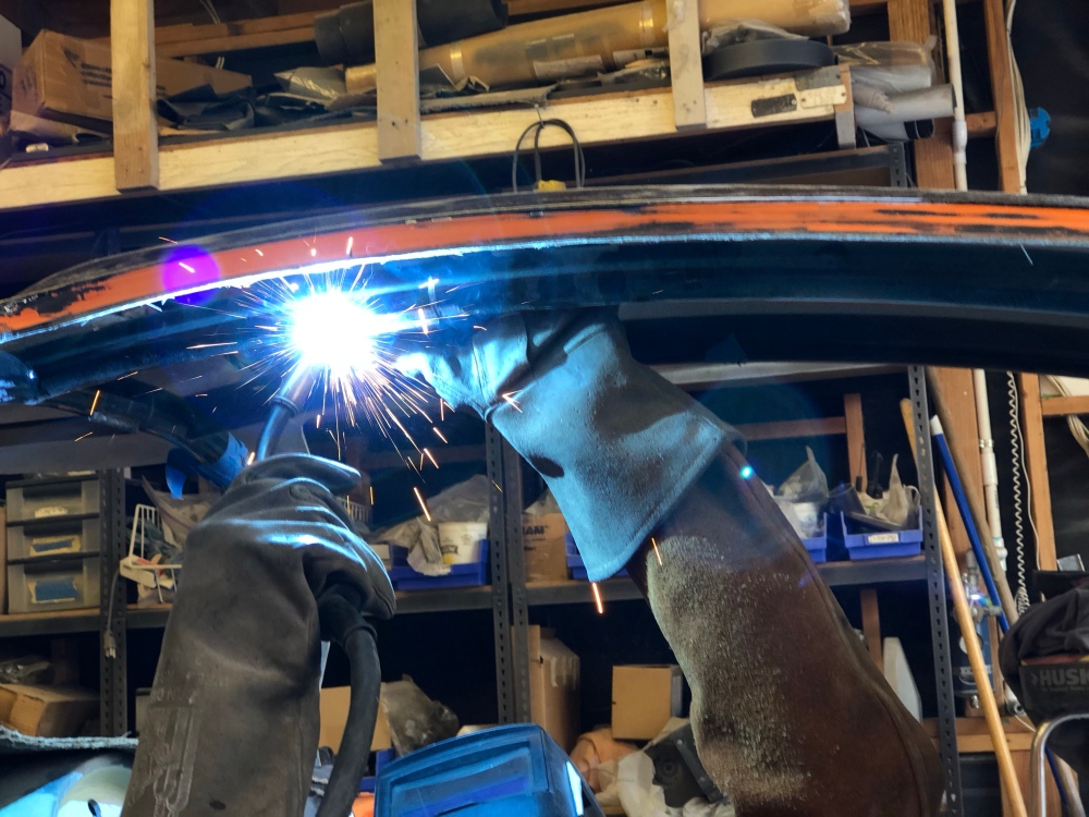
While I was messing around getting all these pieces to fit I had Bob give me a hand with some welding. As I said, I don’t want drill holes into my roll cage – but I need to mount my rear view monitor onto the ceiling. I had Bob cut a rectangular piece of steel that he then welded to my two overhead bar. I’ll add some rivnuts to this plate so I can add a drop-down bracket that I’ll then use to support my monitor. I plan to also throw a few screws in from below to secure the ceiling panel in place.
Gettin’ miggy with it!
Radiator air duct:
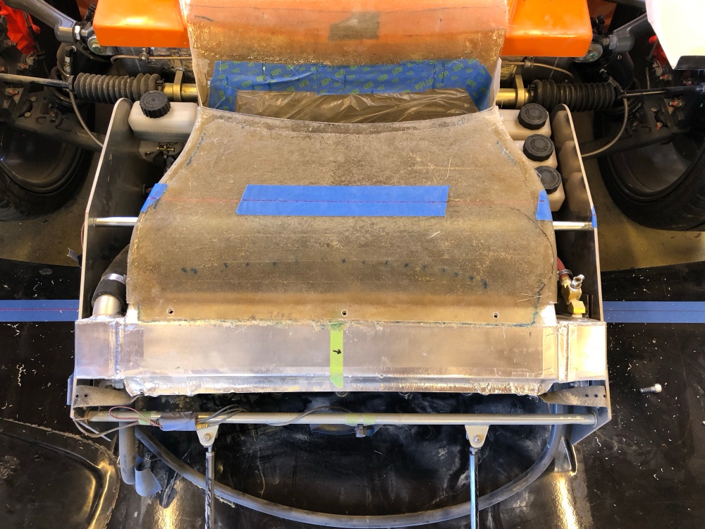
In post 28 I discussed how I fabricated my radiator discharge duct. To install this duct meant I needed to remove the upper cross-brace for the radiator box. It was originally installed where my clutch master cylinder reservoir is currently installed so it needed to go anyway. However, the upper part fo the radiator box isn’t as stiff as I’d like so this bar needs to go back in. In its originally location, I believe it was located too far back. The rear area of the radiator box is actually fairly well secured and stiff because this is where it’s mounted to the footbox. Where’s it’s weakest is right in the middle – and this is where I want to locate it. Unfortunately, it means I need to skewer my radiator air duct.
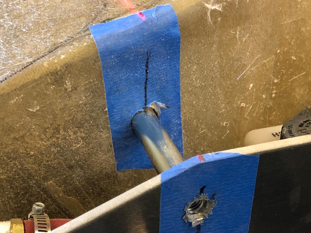
I plan to add some additional struts to support the outermost area of my splitter. The interior attachment point will be the radiator box – so I want the cross-bar to be located as close to this location as possible to achieve maximum support for the struts. Now that I’ve figured out where these struts will go, I was able to mark out the new location for my cross-bar. Using my laser and a tripod, I was able to transfer hole locations from left to right before the drilling began.
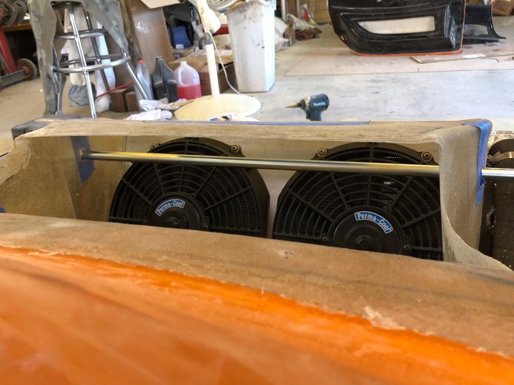
Cross-bar punches through the air duct and is secured to the radiator box via two bolts on either side.I believe its size and location is fairly minimal and shouldn’t negatively impact the air flowing out the radiator fans.There’s a small gap between the cross-bar and air duct but I don’t think it’ll make much difference.
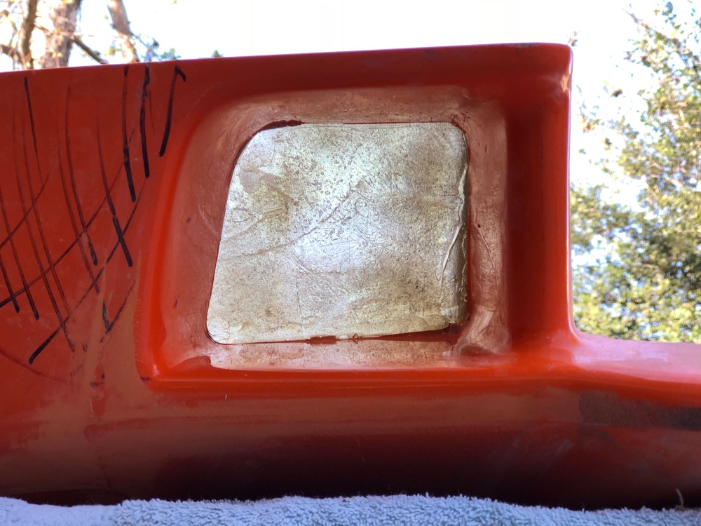
Fog lights recess:
On either side of the radiator inlet are two squarish shaped openings which lead into the cavity just forward of the front wheels. I’ve seen several folks use these inlets to pull fresh air for front brake cooling. Since this is going to be a street car I don’t plan on running brake cooling – so I won’t need these for that.
I’m also planning to install the wheel well liners which will effectively close off this cavity and completely separate it from the front wheel wells. So if I leave these two inlets uncovered I’ll be pushing air into the nose of the car, with nowhere for it to go – sounds like a potential recipe for mucking up the front end aero. So I’ve decided to block them off.
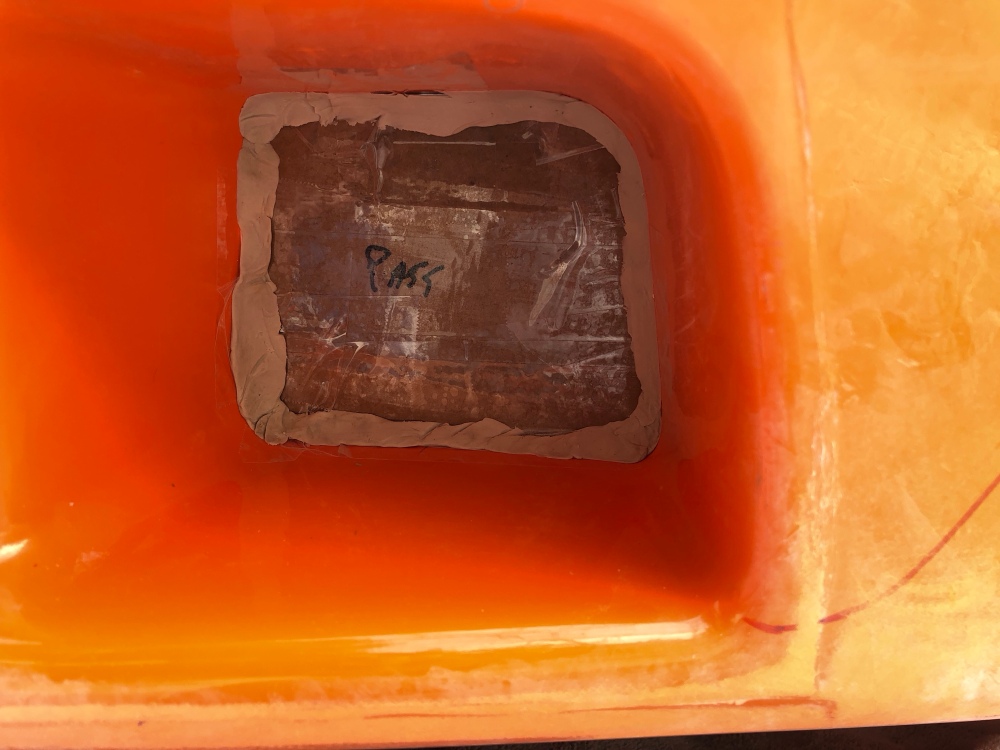
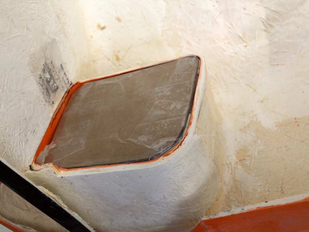
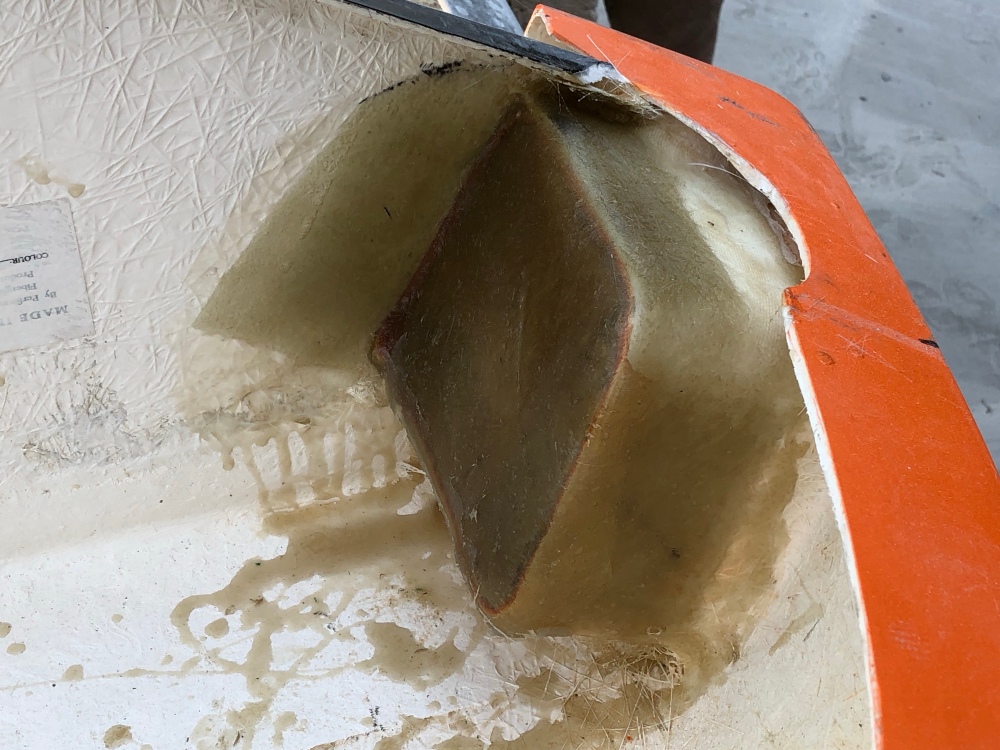
^^ These guys right here ^^Cardboard and packing tape to the rescue!The interior bits need trimming to square them up with vehicle centerline.I glassed the entire hole in – but I plan to cut out the interior, keeping the outer edges to create a flange that I can then bolt a plate onto.All covered up with nowhere for air to go!
For the time being my plan is to make a small cover plate that I’ll then mount fog lights onto. If in the future I decide I want to run brake cooling it’s a fairly simple job to make a new plate and the flange will provide a secure mounting location.
On the subject of the front wheel well liners – I haven’t installed these yet because there are a good number of considerations which need to be addressed before the liner can be bonded into place. More discussion on this in a later post!

2 Comments Add yours