It seems there are a good number of areas I’ve been approaching with trepidation, I’m really starting to sound like a broken record! … well, add to it the engine coolant and air conditioning systems. It took me a while to figure out how to configure and mount the coolant plumbing. The LS cooling system – the thermostat in particular – took a fair bit of reading and thinking about before I felt comfortable tackling this portion of the build. I had read the how-to on configuring the Vintage Air AC unit but I haven’t come across a build thread that discusses this area in detail. It seems everyone’s got their own solution on how they crammed the VA system into their car and they’re all different. The latest generation of VA systems locates the fittings and orients them such that they crash immediately into the side of the footbox. Modifying these to work with the SLC made me nervous – on past cars where I’ve monkeyed with the AC I’ve inevitably crushed or cracked a line and had to call on a pro to fix my snafu.
LS coolant system:
I opted to use the “low buck” method of constructing the radiator piping as described in the wiki. The idea behind the low buck method is to purchase a hose with multiple bends that can be cut into pieces to make the required bends for each side of radiator. A second hose is used to join the straight sections to the radiator inlet and outlet. I purchased the Dayco C71903 hose and this seemed to work decently well for getting 90s and 45s. However, Dayco hose 70885 may have somehow changed over the years since this method was devised. The hose I got appears to have been formed in multiple planes whereas the photo shown on the wiki makes it appear as though those hose should be in a single plane. Whichever the case, I believe the radiator design has also changed since the Low Buck method was devised. In an earlier design of the radiator, both inlet and outlet pipes were located at the BOTTOM of the radiator. Today’s current design has the inlet coming in at the lower left and the exit at the upper right. So using the same hose to route to two different locations (if following the Low Buck method) doesn’t make much sense. After twisting and hacking up the hose a bit I was eventually able to come up with a solution that “works”. The passenger side hose needs an additional few inches of straight hose added between it and the radiator. It’s not the prettiest solution and in hindsight I’m wondering if I may have been better off just going with flexible coolant hose altogether. The cost differential isn’t likely to be much and it may provide a cleaner look.

To insulate the straight sections I ordered rubber based Buna-N foam insulation from McMaster (PN 4463K128) and am using 8863T85 clamps to secure the insulated lines. In all, I needed 3 pieces of foam insulation to cover everything (insulation available in 6′ sections). I plan to push the insulated pipes as far away from the passenger side rails as possible so I’m holding off on securing things until I can get the center spider section back on to ensure I don’t have an interference issue later. I’ve read of several instances where SLC builders have experienced a fair bit of heat in the passenger compartment and I’m doing everything I can to address this so it’s not an issue for me. A note on the insulation – it’s fairly fragile and will require some type of protection if it’s going to be exposed to road debris. I’m going to try running some Gorilla Tape around it to give it just a little bit of abrasion protection.
I had planned to mount my surge tank (Canton PN 80-200) on the upper firewall, behind the driver’s head but I knew the bodywork overhangs this area by a fair amount. After trying some rough test fits it seems I’d have to hang it out a few INCHES to get the cap exposed enough to get line of sight on it with the center spider mounted. I’ve seen other builds where the expansion tank is bolted right to the firewall and a small hole is cut into the bodywork to facilitate filling of the tank. It took me a while but I think I eventually found a compromise that gives me line of sight access to the tank – it would have been awesome if I could source one of the SLC-specific expansion tanks but the second group buy seems to be lagging and timing won’t work for my build.


LS cooling discussion:
I wanted to spend some time discussing the LS engine, its cooling system, and how to set it up for the SLC. It took me quite a while to understand how the cooling system ought to be plumbed and it was because I didn’t really understand how the system works on the LS. I’m betting there are others out there in a similar situation so hopefully this next bit is useful to you.
The discussion that got me pulling on this thread is it’s very common for LS owners to purchase the “Chevs of the 40s” heater control valve (HCV) in lieu of using the kit-supplied electronic heater control valve (manufactured by Vintage Air). Note that the kit supplied by RCR actually includes TWO HCVs. The first is a simple on/off pneumatically actuated valve included with the base VA air conditioning unit. The second is an electronically adjustable unit sourced by RCR (also made by VA) to include as an alternative to the on/off pneumatic version. Why would RCR pay extra for a valve no one wanted?? I scratched my head for a while looking for posts which discussed the reasons for this and couldn’t find one that succinctly summarized the topic until I came across this link from the “cooling system” section of the wiki. The primary issues/scenarios discussed were the following:
- It’s possible the LS motor may overheat if you use an HCV that is fully closed during engine warm-up. With the kit-supplied configuration this can happen if the AC is switched on as it places the HCV in its fully closed position.
- LS owners who have deleted their heater cores and plugged the in/out ports on the back of their water pump have reported higher typical operating temperatures.
I couldn’t find any explicit examples of SLC owners running LS motors who actually encountered this issue though I may not have dug far back enough. I couldn’t find the origins of when the Chevys of the 40s valve was accepted as the de-facto SLC HCV. To understand how these scenarios might occur one needs to understand how the thermostat works on the LS motor. The thermostat on an LS motor “sees” coolant flowing across the INLET side of the heater core ports. In the case of an engine where the heater core is deleted and these ports are blocked, the thermostat isn’t seeing enough coolant flow across the wax pellet and therefore doesn’t get hot enough to open before the coolant circulating within the engine has gotten too hot. Keep in mind – if the thermostat doesn’t open, the coolant here is dead-headed and the majority of circulating coolant is that which is already running within the engine block. The point of this is to help the engine warm up quickly – one of those pesky emissions things since the engine runs better/cleaner when it’s up to temperature and the engine manufacturer wants to get it there as quickly as possible.
So what about the SLC, and why is it an issue to use the kit-supplied valve? If using the kit-supplied valve, the VA system will default the HCV valve to fully closed if the system is set with the AC in the on position. This would then effectively create the heater core delete scenario described above with one exception. The typical LS motor is plumbed per the sketch below (credit goes to DCarter for this image).
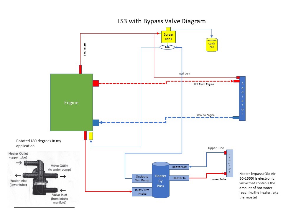
In the image above you can see there is a hose running from the bottom of the surge tank and teed into the line coming from the heater core/HCV (or INTO the back of the water pump). There is also a “steamline” plumbed into the top of the surge tank. If one were to start the engine with the AC enabled, a small circuit of hot coolant will form; the steamline will transport steam (and some liquid) up into the surge tank. The water pump will then draw some of this heated coolant down through the bottom, past the tee, and into the back of the water pump where it will flow across the thermostat. Run the motor long enough and the thermostat will get hot enough to open. However, the amount of coolant running in this circuit is so minimal it’s likely your engine will overheat before the thermostat has reached a high enough temperature to open. So that’s no good.
What does this Chevys of the 40s valve do that the kit-supplied one doesn’t? The key is in how Dan labeled the HCV in his schematic – here, he’s referring to it as the “heater bypass”. It turns out this particular valve creates a bypass loop that circulates coolant from the 5/8″ OUT port and runs it right back into the 3/4″ IN port when the HCV is set to fully closed. The wiki suggests if you’re going to delete the heater core then a bypass circuit should be created to avoid the thermostat staying closed for too long.
I really didn’t want to have to buy another part I already had TWO of just to get this bypass functionality. I discussed this with Bob for some time and he came up with the idea of implementing an orificed bypass loop configured before the kit-supplied HCV. If the HCV were fully closed some amount of coolant would be circulating and running across the thermostat to open it up before the engine got too warm. If we sized the orifice small enough we could still maintain a fairly decent flow of hot water to the heater core if we really wanted to run the heater. Since this car is located in San Diego the chances of me wanting to turn the heater on are fairly low. The chances I would want the heat on full blast are basically zero. I figured having a less efficient heater core circuit would be an acceptable solution if it meant I didn’t have to spend another $100 buying a THIRD HCV for this car.
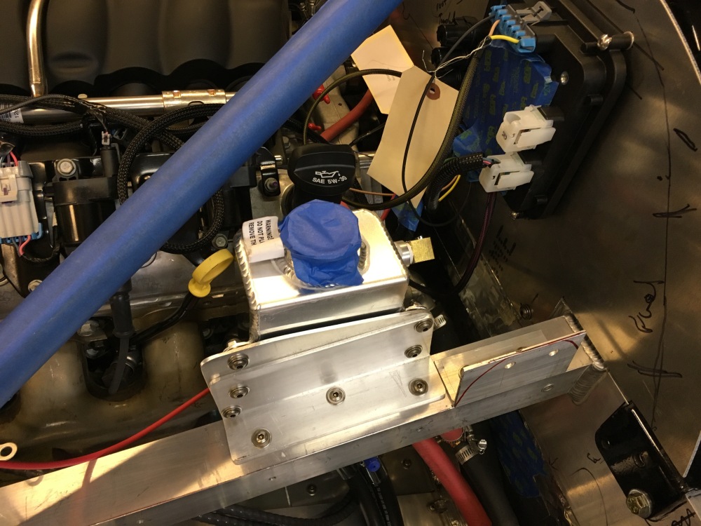
So here’s how we did it:
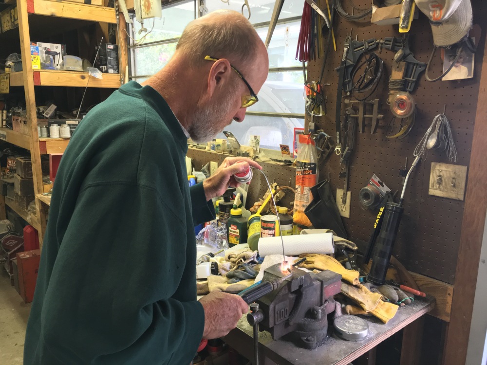
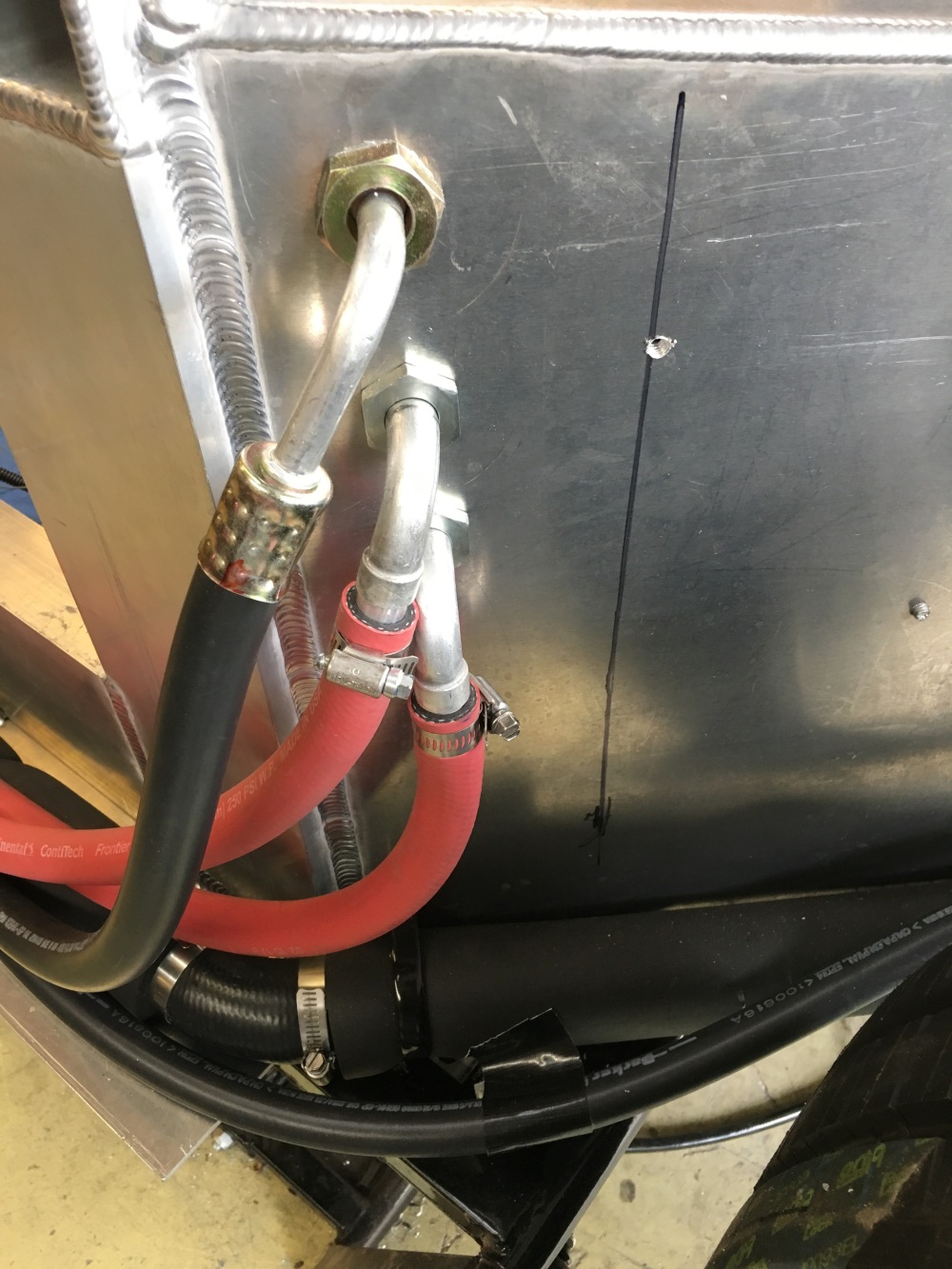
Bob happened to have 2x tees which had 5/8″ hose fittings on either side with a 3/8″ NPT female port in the middle. We could create our bypass loop by joining these two tees together using a 3/8″ close nipple. To create an orifice, Bob came up with the idea of filling the close nipple with solder then drilling it out to whatever size orifice we wanted. I was a bit worried about the solder failing over time but Bob felt pretty confident it would hold up just fine – cool, let’s do it!


I believe the way Dan has his schematic laid out is the “optimum” way to configure an LS motor for the SLC. One additional topic that bears discussion is the surge tank. The surge tank brings with it several benefits. I won’t go into those in this post though a VERY thorough discussion of the surge tank and its role in an engine cooling system are covered in the link from above (and once again here). One very important benefit of running a surge tank, and key for the SLC, is it allows the builder to place the radiator cap at the lowest pressure point in the engine cooling system. Why is this important? The Cliffs Notes version is the location of the radiator cap can control overall maximum system pressure based on where it’s installed.
Most everyone knows water will boil at 212 deg-F. This is true if you’re at sea level. If you’re in Denver the boiling point of water is 203 deg-F. The lower boiling temperature in Denver is due to the decreased atmospheric pressure from being at high altitude. Going back to the importance of pressure within an engine cooling system – the pressure is not equal throughout, therefore coolant will actually boil at different temperatures depending on where you are in the system. What’s the pressure distribution look like in our engine systems? Generally speaking, the highest pressure is at the water pump outlet and the lowest pressure is at the water pump inlet. If your radiator cap rated at 16 psi were placed at the water pump outlet then the maximum pressure in your system would be 16 psi – any more pressure developed by the pump would be lost as the radiator cap would open and vent any extra pressure. However, if that same radiator cap were placed at the water pump inlet, the maximum pressure at the water pump outlet would now be some number higher than 16 psi (say 30 psi). This means the coolant coming out of the water pump would have a boiling point of 273 deg-F due to the higher pressure – not bad!
Here’s some key text I’ve pulled from the site linked above:
As we previously discussed, because pressure drop increases as the coolant flows from the pump, through the system, and back to the pump, system pressure is not equal everywhere. This is an important consideration in rad cap location. The rad cap operates on the system pressure at its location. If it were located in the highest pressure portion of the system (the pump outlet or radiator inlet), it would regulate system pressure based on that highest pressure, meaning pressure elsewhere (for example, in the back of the cylinder heads) would be something less than the rating on the rad cap. This could mean pressure in the critical engine passageways could be as much as 10 PSI or more lower than the rad cap pressure rating – which is not good for cooling performance. It’s also difficult to accurately measure system pressure at all locations, so you probably wouldn’t even know how low the pressure was in the cylinder heads with the rad cap installed in the high pressure side of the system. In other words, with this arrangement, you may install a 20 PSI rad cap and expect coolant boiling point to be 259° F, but actual pressure in the heads, where boiling would occur first, would be less – perhaps only 10 PSI, and therefore actual coolant boiling point would only be 239° F – some 20° F less than you think! For this reason, the rad cap must be located on the low-pressure side of the system – either on the appropriate rad tank or on a remote-mounted surge tank.
In the case of running either the kit-supplied HCV or the Chevys of the 40s unit, overall system pressure will be higher if the bottom of your surge tank is plumbed into the 3/4″ IN port at the back of the water pump. To be clear, the surge tank should be plumbed at the lowest PRESSURE point in the system, but physically located at the HIGHEST point in the system.
Vintage Air AC:
The Vintage Air evaporator/blower unit comes with an AC control knob hooked to a copper capillary tube inserted into the evap case. The knob is mounted via 2 small screws to the side of the case. In this location, the knob interferes with the center beam dividing the passenger footwells; so I removed the 2 screws and pulled the tube out of the box while I modified the unit to better fit the SLC chassis. Unfortunately, as-delivered, the 4 hose connections running out of the evap unit don’t work very well if you’re trying to install the case under the passenger side dash.

First up – the expansion valve points right into the side of the passenger footbox. There’s no room to install any kind of fitting without it crashing through the side of the footbox – it requires re-orientation. I removed the black sticky goop surrounding the expansion valve. This exposes the b-nut securing the valve. Work the copper line loose so you’ve got room to get a wrench on the nut and back it off. I then turned it about 90-deg (so it points “down” relative to mounting orientation) and hand tightened the nut.


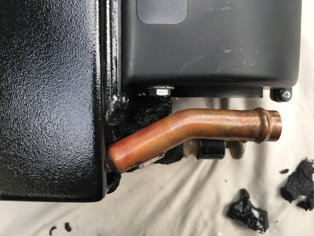
As delivered, the two 5/8″ heater core lines point right toward the side of the footbox. In this orientation it’s virtually impossible to get a hose onto the lines to turn the flow quickly enough for the VA unit to fit under the dash. I struggled for quite a while trying to figure out what to do. I contacted SHackett and he told me he’d bent the heater tubes by hand and it worked for him. As I said before, I’ve had run-ins with bending HVAC tubes in the past and they didn’t turn out very well for me – so I wasn’t too keen to just bend the tubes without digging into it a little further. The tubes are covered with what appears to be black silicone. I cut this away from the tubes so I could see what they looked like as they enter the evap case.
Upon closer inspection it looks like the 5/8″ tubes are brazed onto a smaller set of tubes. It appears the heater core is made up of ~1/4″-3/8″ copper tubing; the 5/8″ tubes are then attached to the ends of the heater core coil. With all the silicone removed I could clearly see the tubes; some fairly light thumb pressure and I could get the heater core tubes to bend away from the footbox; note the 5/8″ tube is too stiff to bend so the bending is actually happening at the smaller tubes. I was able to bend the tubes ~20-30-deg away from the footbox; this would give me just enough room to install some formed 90-deg heater hose. This allowed the heater core hoses to turn quickly enough it didn’t interfere with the footbox when installing the evap box under the dash.


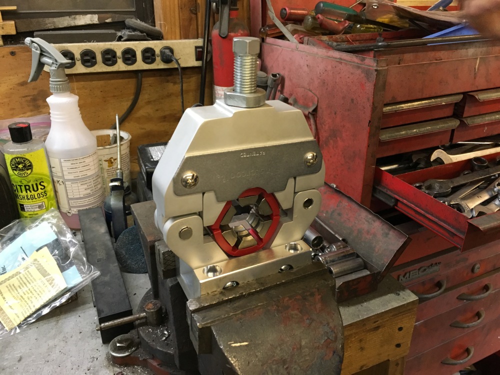
The supplied AC hoses are beadlock type and require a fairly heavy duty tool to crimp. Fortunately Bob has made many AC hoses for his project cars and his crimping setup came in handy here!


Mounting of the condenser was fairly straightforward; I used the supplied mounts and bolted the condenser approximately 3/4″ in front of the radiator. I believe the “magic number” is 1/2″-3/4″ in front of the radiator for best efficiency. I mainly shot for positioning the condenser ahead enough such that any movement due to vibration/bumps would not cause it to impact the radiator – it just happened to turn out about 3/4″ in front of the radiator.
Prior to mounting the evap box I reinstalled the copper capillary tube and taped it into place. I then routed the control knob next to, and down the side so I could clear the front bulkhead cross-beam. I plan to mount the AC control switches either within the center binnacle or just right of the center console.

I’ve still got a few more crimps to run then the more complex job of wiring everything up and getting it all to work together – just super happy to have gotten the VA unit mounted without destroying the tubes.
